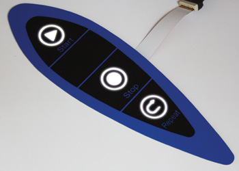
The engineers at Pannam can integrate backlighting into your membrane switch using any of four different technologies (Light Emitting Diodes (LEDs), Electroluminescent (EL) Lighting,
Fiber Optic Lighting and Light Guide Film) depending upon your requirements. This document focuses on Light Guide Film – what it is, when to use it and considerations prior to designing your switch.
What Is Light Guide Film (LGF):
LGF is a thin film that will direct light produced by side-firing, or right-angle, LEDs across the area that needs to be backlit. The film is placed directly below the graphic overlay and above the circuit layer so that the light will not be obstructed by any circuit traces or tactile devices. This film can be cut into any pattern or shape within your switch. Multiple LGF films can be used within one application to provide discrete backlighting to different graphic features. Different colored LEDs can be used to achieve unique lighting effects or white LEDs can be used to light different printed graphics on the overlay.
Because LGF is simply a conduit for the light produced by LEDs, the film must be adjacent to a right-angle LED. The placement of the LEDs within your switch depends on several factors and will be determined by the Pannam engineering team.
When to Use (and Not Use) Light Film Guide for Backlighting in Your Switch:
Although LGF is often a more expensive backlighting option (relative to the others), it has several advantages:
- The LGF is extremely thin so it can be incorporated into membrane switches that can’t exceed a certain thickness (i.e. small, lighter devices)
- LGF has limited impact on the tactile feel of buttons.
- It can provide even backlighting across large and small areas, and for applications where the light remains on while the switch is powered.
Weaknesses of LGF are that it can sometimes allow light leaks and hot spots – both of which can be overcome by proper design. LGF is a poor choice for lighting the same area with multiple different colors because of the single-source LED light.
Critical Pre-Design Considerations:
Constraints of implementing LGF into your switch design include:
- Allowing enough space for the right-angle LEDs.
- Not allowing enough space between the light source and the backlit areas.
- Distances from LED to backlit area, # LEDs/area backlit, distances between backlit areas (see below for distances chart).
| LTR | DIM (mm) | DESCRIPTION |
|---|---|---|
| A | ≥ 8 | Distance between led and illuminated area. |
| B | ≥ 4 | Distance between discrete illuminated areas perpendicular to light path. |
| C | ≥ 6 | Distance between discrete illuminated areas parallel to light path. |
| D | ≥ 5 | Distance between illuminated area and termination location. |
| E | 0.5 | Distance between edge of circuit layers and edge of overlay. |
| F | ≥ 5 | Distance between light blocking spacer & part edge. |
Other Key Pre-Design Questions to Answer:
- In what type of light will the device be used? Will the backlighting need to be visible in bright sunlight, the ambient light of offices, dark hospital rooms, etc.?
- What needs to be backlit? Is it a full screen, keypad, specific buttons, status or discrete indicators, a combination?
- What colors will be used and where?
- What are the power requirements?
- What are the space constraints?
- If there is a keypad or buttons, what type of tactile feedback is required?
Other Backlighting Options:
| Light Emitting Diodes (LEDs) | Point source indicator lights; ideal when lights must cycle on/off and/or need multiple colors. |
| Electroluminescent (EL) Lighting | Ideal for rubber key pads installed in low and no light environments; typically single color applications where the backlight is not always on Fiber Optic Lighting Best for uniform backlighting across a broader area. |
| Light Guide Film | Ideal when a consistent backlighting color needs to be provided to several elements in a switch. |
Pannam Design Process & Support:
Step 1 (Technology Fit Assessment)
- Determine if membrane switch is the right technology for your human/machine interface.
- Compile application information (operating environment, function/use, etc.); drawings if you have them.
Step 2 (Application Specification)
- Request information about various switch types/materials – schedule a phone consultation or technical sales call.
- Considerations:
1. Operating conditions (indoor/outdoor, chemicals, etc.)
2. Mechanical requirements (tactile feedback, actuations, etc.)
3. Electrical requirements (layout, resistance, etc.)
4. Appearance (color, texture, etc.)
5. Certifications (ISO, UL, etc.)
Step 3 (Design)
- Submit quote request.
Step 4 (Quotation)
- Receive quotation / re-design amp; re-quote if required.
Step 5 (Production)
- Approve quotation and begin production. Shipment.


